Networking Model 1: L2 and L3 Network
ZStack abstracts the networking model into L2 and L3 networks. An L2 network provides a type of L2 isolation method, while an L3 network basically represents a subnet associated with OSI layer 4 ~ layer 7 network services. The idea is to use terms and concepts with which administrators have been familiar to describe ZStack's networking model, allowing administrators to create networking topologies easily and precisely.
Note: We will not involve any details about network implementation at hypervisor side; for example, we will not discuss how ZStack creates bridges or VLAN devices in the Linux operating system. The purpose of this article is to give you a brief idea of ZStack's networking model. We strongly recommend you to read The Versatile Plugin System if you haven't, as many terms related to plugins(especially the extension point) will be mentioned in following contents.
Overview
The most exciting and difficult part of a cloud must be the networking model. The biggest revolution the cloud technology brings to traditional datacenters is that administrators won't have to spend days or weeks in creating or changing networking topologies, instead, they can finish the former daunting task in a few minutes by clicking some buttons in the UI of IaaS software.
In order to achieve that simplicity, an IaaS software must have a clear and flexible networking model that can help administrators build the majority of classic networking topologies of traditional datacenter in the cloud. And, what's more, it must allow administrators to change the well-built network whenever necessary without redeploying the entire cloud.
The overall picture of ZStack's networking model is like:
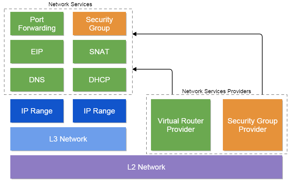
An L2 network, which represents exactly an L2 broadcast domain, is the base of all network elements. Upon an L2 network there are L3 networks and network service providers; an L3 network is a subnet with network services associated; despite an L2 network usually contains only one L3 network, multiple L3 networks can co-exist on the same L2 network as long as their IP ranges won't conflict. An L3 network may have one or more IP ranges belonging to the same subnet, the purpose of having separated IP ranges is to allow users to reserve a part of IPs from a subnet. Network services like DHCP, DNS are provided by providers bound to an L2 network to upon L3 networks.
Note: As Virtual Private Cloud(VPC) has not been supported in this ZStack version(0.6), the above networking model doesn't show how VPC will work. However, the concept is similar, the VPC is just a coordination of multiple L3 networks with programmatic routing. We will introduce VPC in future ZStack version, which is coming soon.
L2 Network
An L2 network is responsible for providing an L2 isolation method that can be a pure L2 technology(e.g. VLAN), or an overlay technology(e.g. GRE tunnel, VXLAN). ZStack doesn't care about the details an L2 network uses in the backend, so the data structure -- L2NetworkInventory -- which encompasses necessary L2 information is highly abstracted:
| FIELD | DESCRIPTION |
| uuid | L2 network UUID |
| name | a short name |
| description | a long description |
| zoneUuid | uuid of zone the L2 network belongs to |
| physicalInterface | a string containing information necessary to implement the L2 network at the backend. for example, 'eth0' |
| type | L2 network type |
| attachedClusterUuids | a list of cluster uuid the L2 network has attached to |
A sub-typed L2 network may have extra properties, for example, the L2VlanNetwork has an extra field vlan.
Attaching Strategy
In real datacenters, an L2 network usually represents the connectivity of a physical network between hosts, for example, hosts under the same L2 switch may be on the same L2 network. The network connectivity is not unchangeable, it may change whenever the physical infrastructure of a datacenter changes, for example, administrators re-wire an L2 switch. To provide a flexible way describing relationships between hosts and L2 networks, ZStack uses a so-called attaching strategy that allows an L2 network to be attached/detached to/from multiple clusters that are groups of hosts.
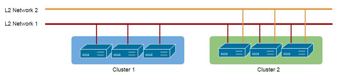
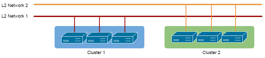
In above picture, hosts in the cluster1 and the cluster2 are all wired to the L2 network1 while hosts in the cluster2 are also wired to the L2 network2, administrators can attach the L2 network1 to both clusters but attach the L2 network2 to only cluster2. Some time later, if administrators re-wire hosts in the cluster2 to remove connections off the L2 network1, they can detach the L2 network1 from the cluster2 to reflect current network connectivity.
The attachment between clusters and L2 networks shows the behavior of establishing L2 broadcast domains among hosts within those clusters, which doesn't always involve physical connection changes. For example, hosts connecting to tagged switch ports can create bridges on ethernet devices with the same VLAN in their operating systems, to build an L2 broadcast domain for VMs connecting to the bridges; in this case, attaching or detaching an L2 network doesn't imply any physical infrastructure change but the behavior of creating or deleting an L2 broadcast domain.
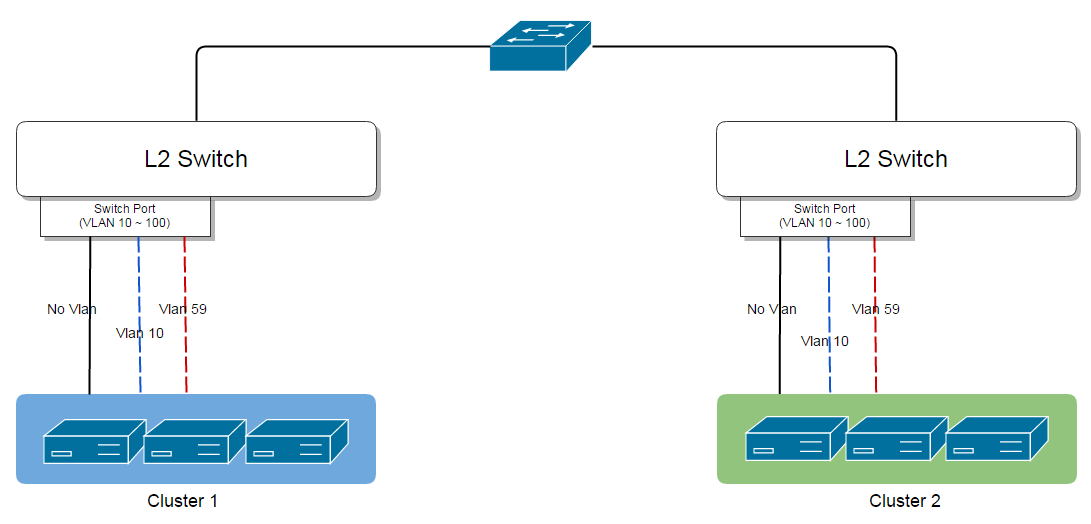
In the above picture, once administrators create an L2VlanNetwork with VLAN 10 and attach it to the cluster1 and the cluster2, a broadcast domain is created among hosts within these clusters. Hypervisors may take various ways to implement the L2 broadcast domain, for example, KVM hosts will create bridges with VLAN devices(VLAN 10) in their Linux operating systems; if the L2VlanNetwork is detached from the cluster2 later, the hosts in the detached cluster will be removed from the broadcast domain by deleting their VLAN(10) bridges. This concept of creating/destroying broadcast domains applies to all types of L2 networks; for example, attaching an OvsGreL2Network to KVM clusters may lead GRE tunnels to be created amid hosts, while detaching an OvsGreL2Network may cause GRE tunnels to be deleted.
The attaching strategy has an extra bonus in with respect to restricting hosts that VMs can run. Because a VM is always created with L3 networks belonging to some L2 networks, the VM will only be allocated to a host in the cluster that has been attached to those L2 networks. By this way, administrators can divide hosts into different pools by L2 networks, for example, clusters attached with a high bandwidth L2 network, clusters attached to a public L2 network. If administrators want to put all hosts into a single pool, they can attach all L2 networks to all clusters.
Backend Implementation
With virtualization technology, the backend implementation of an L2 network is highly hypervisor dependent. For example,
the implementation of the L2VlanNetwork on a KVM host is creating a bridge with a VLAN device but configuring a vSwitch on a VMWare ESXi host.
To decouple the implementation of L2 network from hypervisors, ZStack delegates the responsibility of implementing a type of L2 network
to hypervisor plugins. Two extension points are defined for realizing an L2 network. The first one is L2NetworkRealizationExtensionPoint:
public interface L2NetworkRealizationExtensionPoint {
    void realize(L2NetworkInventory l2Network, String hostUuid, Completion completion);

    void check(L2NetworkInventory l2Network, String hostUuid, Completion completion);

    L2NetworkType getSupportedL2NetworkType();

    HypervisorType getSupportedHypervisorType();
}
When an L2 network is being attached to a cluster, this extension point is called for every host in the cluster, the hypervisor plugin
can take this chance to implement the network on the back-end host; for example, the KVM plugin has both KVMRealizeL2NoVlanNetworkBackend
and KVMRealizeL2VlanNetworkBackend that extend L2NetworkRealizationExtensionPoint to create bridges on Linux operating systems.
This extension point is useful for L2 networks that don't need to know information of VMs, both L2NoVlanNetwork and L2VlanNetwork
fall into this category. However, some L2 networks may only be able to be implemented when VMs are being created, for example, an L2VxlanNetwork may
need to look up the VID of a VM's owner account in order to establish an L2 broadcast domain; in this case, the hypervisor plugin can implement another extension point PreVmInstantiateResourceExtensionPoint:
public interface PreVmInstantiateResourceExtensionPoint {
    void preBeforeInstantiateVmResource(VmInstanceSpec spec) throws VmInstantiateResourceException;

    void preInstantiateVmResource(VmInstanceSpec spec, Completion completion);

    void preReleaseVmResource(VmInstanceSpec spec, Completion completion);
}
Plugins can retrieve information of the destination host and the VM from VmInstanceSpec then realize an L2 network before the VM being created
on the destination host.
L3 Network
An L3 network is a subnet created on an L2 network, associated with network services; it can have multiple IP ranges as long as they belong to the same L3 network and won't conflict with each other.
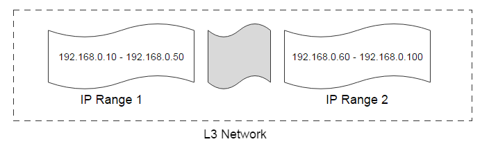
In the above picture there are two IP ranges (192.168.0.10 - 192.168.0.50) and (192.168.0.60 - 192.168.0.100), IPs from 192.168.0.51 to 192.168.0.59 are reserved so administrators can assign them to devices not managed by ZStack.
An L3 network is nothing if without network services that are provided by network service providers associated with the underlying L2 network. A network service
provider may provide one or more network services, for example, ZStack's default virtual router provider is able to provide almost
all common network services like DHCP, DNS, SNAT and so on, while F5 provider may only provide load balancing. In this ZStack version(0.6),
a network service provider can only associate with an L2 network at the time the L2 network is being created; for example, the virtual router provider
implementing L2NetworkCreateExtensionPoint will create associations with all L2 networks after they are created.
Administrators can attach network services to an L3 network; for one type of service, only one service of one network
service provider can be attached to the L3 network; for example, you cannot attach two DHCP services from different providers to the same L3 network.
In this ZStack version(0.6), six types of network services: DHCP, DNS, SNAT, EIP, Port Forwarding, and Security Group are defined, providers
only need to implement corresponding backends: NetworkServiceDhcpBackend, NetworkServiceDnsBackend, NetworkServiceSnatBackend,
EipBackend, PortForwardingBackend, and SecurityGroupHypervisorBackend to provide those services. We will discuss
our reference provider virtual router provider in Networking Model 2: Virtual Router Network Service Provider, you can explore more
details then.
Summary
In this article, we briefly explained ZStack's networking model. Without digging into backend hypervisor details, we demonstrated how ZStack abstracts the OSI model into L2 network(layer 2), L3 network(layer 3), and network services(layer 4 ~ 7). In next article, we will elaborate our reference implementation of the network service provider: virtual router provider, about how it implements DHCP, DNS, SNAT, EIP, and Port Forwarding in an appliance VM.